|
|
|
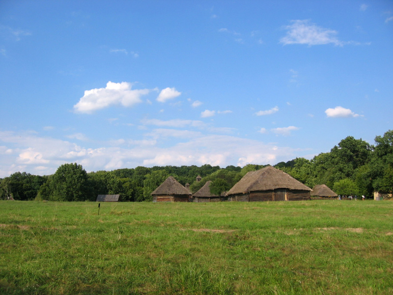
First, we have to find a proper image. Not ideal one , like a golf field
or the standard Windows XP desktop picture. I have browsed many photos,
to find some rough enough. See Fig. 1.1.
I think, that these old huts can be used as realistic background.
Many villages in that region looked similar, in that time. Let's say, that
the airfield could be placed in the nearby.
It is very important to find a place with proper, short grass.
Some empty spots of the ground can also appear, there.
To follow this tutorial: click right mouse button on the Fig. 1.1.
Select Save image as command from the context menu, that will appear.
Save this picture as chutor.jpeg in the Background/ subdirectory
of unzipped La-5 model file.
(The word "chutor" is from Ukraine, and means "village".
In fact, this is a picture from an Ukrainian skansen.)
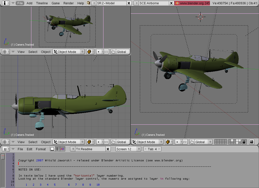
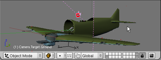
Open downoladed model La-5, and pose it for the ground scene (open the undercarriage, turn the flaps down) – see Fig. 2.1. (You can quickly "pose" the airplane, using HandlePanel script. It is described in another tutorial - notice especially its section 3.).
|
By the way: reduce number of layers, during edition, if the response time of your program is too long. On my machine (see its parameters here) Blender slows down at about 300 000 visible faces.
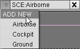
It is practical to create a separate Blender scene for this ground airfield environment. In single Blender file you can have many different scenes, that share the same model data. (The same object can be referenced in every scene). Each scene can have its own set of lights, cameras. Let's cerate a scene named “Village”:
| To start, select the ADD NEW command from the list of the scenes: |
|
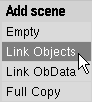
From the Add scene popup menu select Link Objects option: |
|
It seems, that nothing has changed? Well, it is just the effect of linking everything from
the previous scene.
Notice, that we are in the new scene:  .
.
Let’s change its name at once:  - to Village.
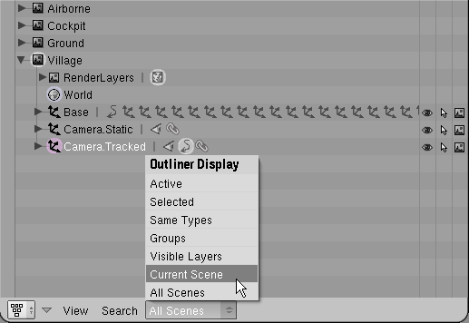
Now – let’s open the Outliner window. You will see the difference (Fig. 2.2):
|
We have now separate “tree” for each scene. On the picture you can see all the “old” scenes – Airborne, Cockpit, Ground. There is also our new scene, named Village. To eliminate possibility of mistake, I would propose to select Current Scene search mode, like on Fig. 2.2.
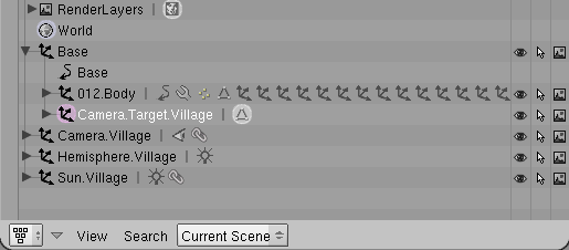
At this moment the Village scene is a copy of the Airborne scene. Objects, visible on Fig. 2.3, are described in an introduction to La-5 model.
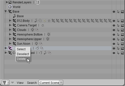
All lights (Hemisphere.*, Sun.Noon, Clouds), cameras (Camera.*) and target (Camera.Traget), are at this moment referenced by two scenes: the original (Airborne) and its copy (Village). In fact the same pieces of data – objects – are linked in both places. When you change the position of Camera.Tracked or its Camera.Target, it will affect both scenes! We do not want change the Airborne scene, so we have to delete all common cameras, lights and target from Village. We will create the new ones, that will be exclusively used by this scene.
This scene has produce a still picture, so we do not need to place lights into the Base frame – just leave it to contain the whole airplane (012.Body element), and camera target. All objects used exclusively by this scene will have “Village” suffix, for easier identification.
Let’s begin - delete the unwanted elements. To learn, how to remove the pilot, see at the end of the description of La-5 model structure. Remove also all cameras, lights and the camera target:
|
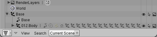
At the end, your scene should look like on Fig. 2.4:
|
You can create new camera, lights and camera target “from scratch”. But, because this file already contains another scene from an airfield – Ground – we can create all this stuff in a quicker way – by duplication. Just:
|
In effect, our scene now contains local camera, lights, and camera target (Fig. 2.6):
|
If you are interesting in details of the light and camera settings – examine their panels in the Buttons Window. I will not show them there, to not expand this, already long, tutorial.
Let’s add the ground to our scene (Fig. 2.7):
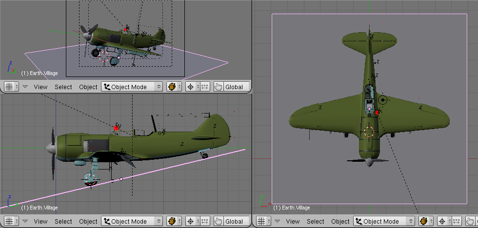
|
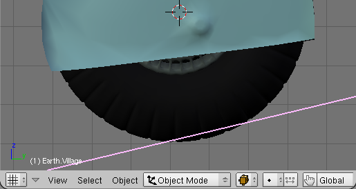
It is a plane, named Earth.Village. It was originally created in the top (XY) view (the 3D View window on the left side of screen from Fig 2.7.) – so it Z axis is pointing upward. Earth.Village was then rotated in the side view (lower, right), around the 3D cursor placed near the centre of main wheels. I have rotated it until it has touched the tail wheel. It was then moved a little up, to “sink” the tips of the wheels in the ground (Fig. 2.8). It will give realistic effect of wheels sunk in the grass.
Notice, that the Z axis of Camera.Target.Village is parallel to Z axis of the ground. Camera.Village has a Track To constraint, which not only tracks the target position, but also aligns view orientation to the target Z axis. Thus on the camera view (upper left 3D view on fig. 2.7) it looks quite natural – that the ground is horizontal, and the airplane has its tail down.
|
Now we do one of the funny things: make the ground follow the camera movement (Fig. 2.9):
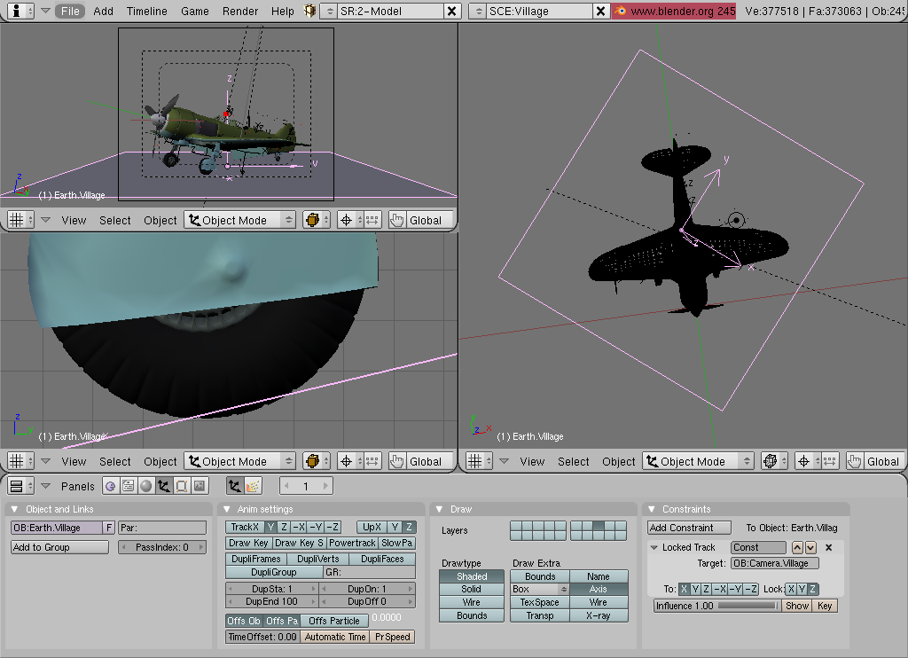
|
To Earth.Village object we have added a Locked Track constraint (see its settings on the rightmost panel of the Buttons window, on the Fig. 2.9). Ground has the Z axis locked – thus the airplane will always stay properly on it! The X axis always points towards the camera. This solution will ensure, that the rear edge of the earth will be always horizontal in the camera view. It is important for final seamless “sink” of the ground into background picture.
 – it is enough for this purpose.
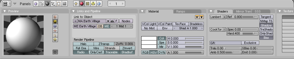
Let’s assign a material to the ground. It has the same name as its object – Earth.Village. It is just white, now. Notice settings on the Shaders panel – Spec = 0 and Hard = 400:
|
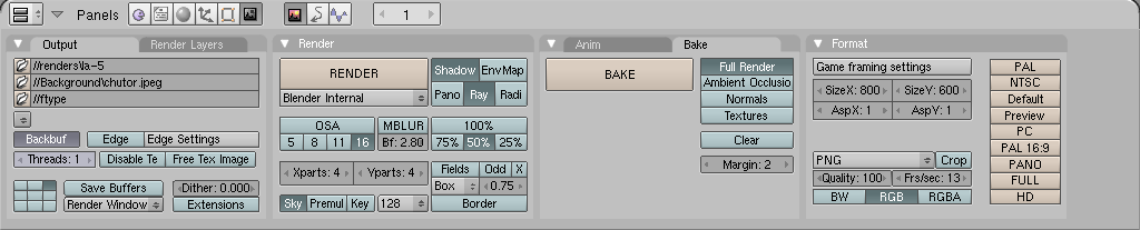
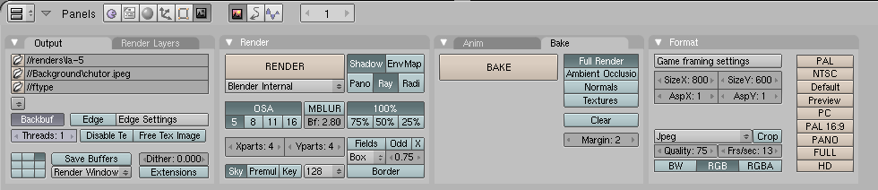
We have also adjust the render settings (Fig. 3.2):
|
Do like I have done on Fig. 3.2: on the Output panel, place the name of the background picture (//Background/chutor.jpeg) and set the Backbuf toggle on. On the Renderer panel, OSA and MBLUR toggles have to be set off. (Turn on OSA for the final rendering – it enhances the edges on the result, but slows the whole process. MBLUR can be used, if you want effect of propeller rotation – but it is not the case of this scene.). The result size toggle was set to 50% - just to speed up the previews. Click on the 100% button, if you want it in the full size. On the Format panel set the Size X and Size Y equal to size of the background picture – 800 x 600, in this case.
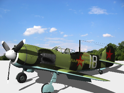
When you press Render button, you will receive following effect (Fig. 3.3):
|
Well, it is not time to do anything with the color of the ground. It is left intentionally white. What we have to fix now:
After some experiments, I would propose to:
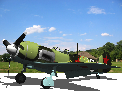
The result, obtained with after these changes, is presented on Fig 3.4:
|
Now we blur the rear end of the ground, visible on the rendering. To do it, we need texture like on the Fig. 3.5:
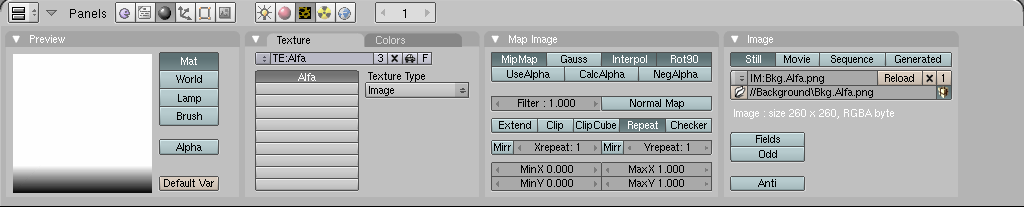
|
This grayscale image was created in Inkscape – a square filled with a gradient. The result was exported into a *.png file.Later note: you can obtain it using the Blend procedural texture, in Blender. I have discovered this simpler way long after this tutorial was finished, and decided to not change it.
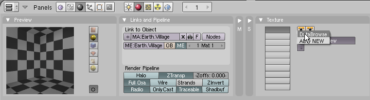
The other settings of this texture are quite normal, and visible o Fig 3.5. In fact, you will find this texture ready to use, in the downloaded model. I have used it in similar Ground scene. It is named Alfa.Let’s add the Alfa texture to the material of Earth.Village. Because it already exists, on Texture panel click the list button (below Add New), and select Data Browse command (Fig 3.6):
|
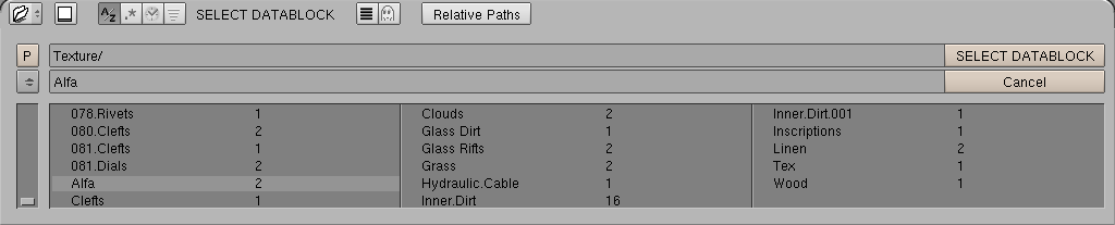
There are plenty of textures (Fig. 3.7)! Click the A/Z button (top left on the Fig 3.7) to ensure, that they are in an alphabetic order. All textures with numeric prefix belong to corresponding model parts. Textures without prefix are “general” – can be used in many different object models. Select Alfa and press SELECT DATABLOCK button.
|
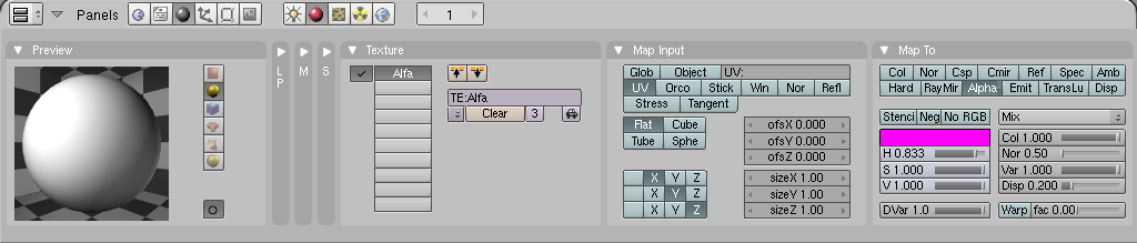
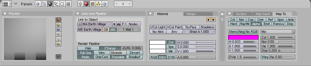
Set settings for Alfa texture in Earth.Village material as on the Fig. 3.8.
|
|
(I have changed the display mode on the Preview panel, on the Fig. 3.9, to show you the effect of the alpha blur)
This is the result, on Fig. 3.10: the border of the ground is blurred.
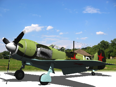
|
We can control the height of the blur, changing the scale of texture mapping in the Y direction. Change the size Y to 0.5 and offs Y to –0.25, like on the Fig. 3.11.:
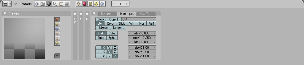
|
This will produce better effect (Fig. 3.12.):
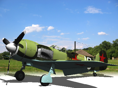
|
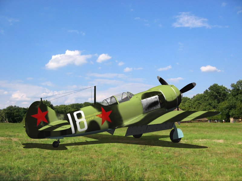
It is time to place the grass on our ground – Earth.Village object. Let’s prepare the texture – the background image (Fig. 3.13):
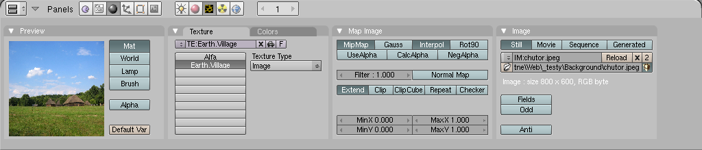
|
This texture is assigned to the Earth.Village material, and – of course – it is also named Earth.Village, to emphasize its dedication. In the Image panel I have selected the same image, which is used for the background (Fig. 3.13).
Next picture (Fig 3.14) shows parameters, which have been assigned to this texture in the Earth.Village material. In fact, the only non-standard thing was done on the Map Input panel. Texture mapping mode was changed to Win. It is important setting. In this mode texture is always perpendicular to current view plane. This means, that it always match the background image. This way we place it “on the top” of the ground plane, which already has absorbed the shadow.

|
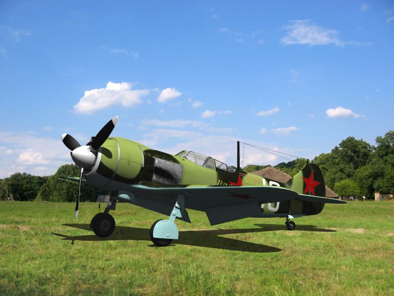
The result looks like on Fig. 3.15:
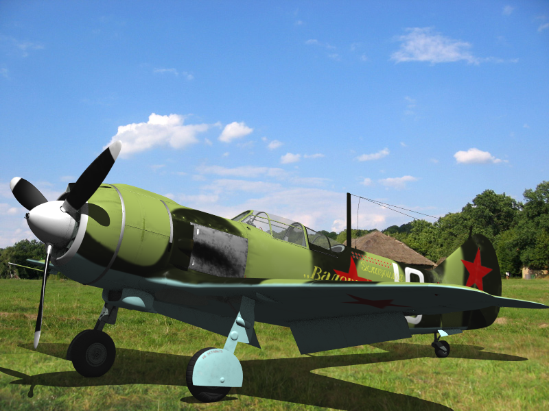
|
Not bad, isn’t it? The texture placed in the Win projection on the ground plane joins the background image without any flaw. (Click on the image, to load its detailed version).
Let’s prepare the “final” version:
(layer 19 – the inner cockpit details – is turned off, because it contains all the stuff that is not visible from the outside);
|
The airplane is more distant, now (see Fig. 3.17):
|
Click the picture to see larger image. I have intentionally made the model less “smooth”, switching the output format to Jpeg with 85% quality. It seems to me, that these small flaws on the model let it better “fit” the background (it looks less artificial).
You can easily change the camera projection – just rotate it around the plane, and the whole scene environment (background and the ground) will properly follow you movements. To keep the effect, rotate camera, together with the sun, around the Z axis of the Earth.Village object, keeping them on constant height above its XY plane. Here is an example (Fig. 3.18), what you can get just rotating the camera:
|
If you are curious, how this final rendering looks like without the JPEG 15% quality loss (set on Fig. 3.16) – here is such rendering (600 kB).
I have also experimented with adding “artificial grass” to make this shadow on the grass irregular. Some effect you can observe on the Ground scene, in the La-5 model. I have created there a mesh named "Grass", and, using the static particle system, generated some grass blades. You can create similar mesh also in this scene. Just copy the settings from the "Grass" material and particle system settings.
I have also found, that turning in the Map To parameters of texture Earth.Village, the Nor(mals) on, with high coefficient (Nor set to 10.00 on the slider - Fig. 3.19):
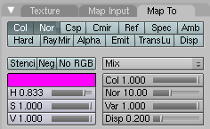
|
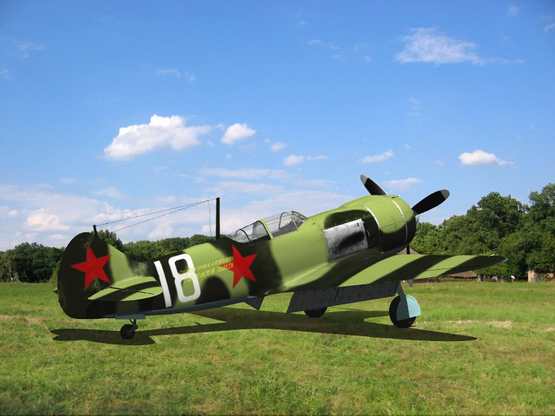
causes the grass on the ground to be more vivid (Fig. 3.20):
|